Hello, welcome to the official website of BolaiKong Technology (Wuxi) Co., Ltd.!
Hello, welcome to the official website of BolaiKong Technology (Wuxi) Co., Ltd.!


Addressing common technical and operational questions regarding valve selection, installation, and maintenance
Double-sided forced sealing for gate valves:
This means that whether at the inlet or outlet end of the medium, the gate plate and valve seat sealing surfaces remain sealed. The sealing integrity is forcibly maintained by the axial force of the valve stem. When no medium is present, the positive pressure between the sealing surfaces must not be less than the sum of the medium's static pressure and the sealing force.
Single-face forced sealing for gate valves:
This means that no seal exists between the gate plate and the valve seat sealing surface at the medium inlet end. Here, either no pressure differential exists at all, or the pressure differential is less than the sealing pressure. On the medium outlet side, the seal between the gate plate and the valve seat sealing surface is forcibly maintained by the axial force of the valve stem and the medium pressure. When no medium is present, the pressure differential across the sealing surfaces must not be less than the sealing pressure.
(1) Classified into two types based on the structure of the gate plate
(2) Classified into two types based on valve stem construction
The minimum stem diameter refers to the diameter of the portion of the stem that contacts the packing. The minimum stem diameter refers to the diameter of the stem thread relief groove.
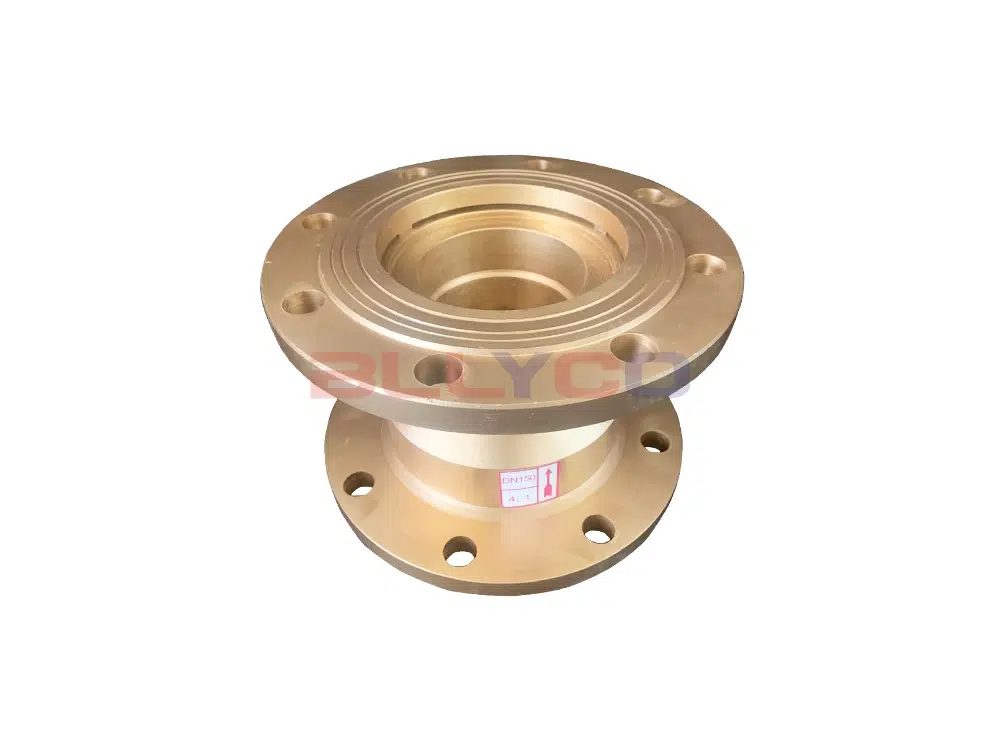
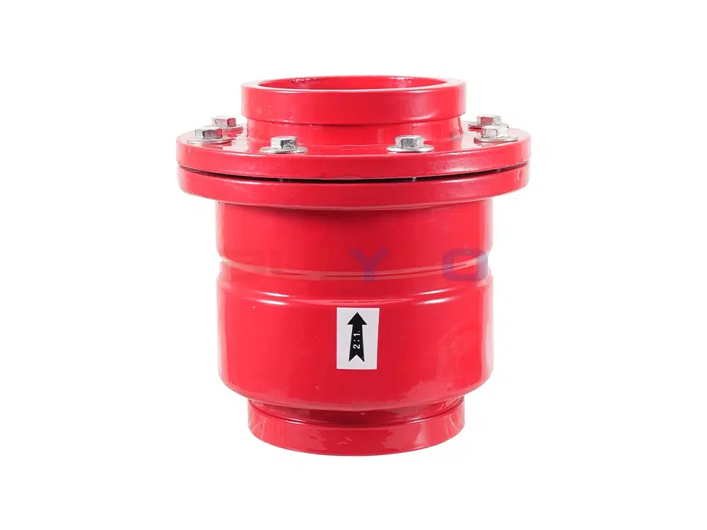
The paint color of the handles and handwheels corresponds to the paint color of the sealing surface material, as detailed in the table below.
Valve handle and handwheel paint color:
Sealing surface material | Handle and handwheel paint colors | Sealing surface material | Handle and handwheel paint colors |
Bronze or Brass | red (color) | Cemented carbide | azure |
pasteurized alloy | yellow (color) | plastics | prune (color) |
铝 | aluminum white | Foundry Iron | ferrous |
Acid-resistant steel, stainless steel | light blue | caoutchouc | medium green |
nitriding steel | lilac | Monel alloy | navy blue |
The opening and closing directions for general valves are specified as follows: clockwise for closing and counterclockwise for opening.
The mandatory and optional markings for general-purpose valves are shown in the table below.
Valve markings:
sports event | symbolize | sports event | symbolize |
1 | Nominal Size DN (NPS) | 11 | Product standard code |
2 | Nominal pressure PN (class) | 12 | furnace number |
3 | Material designation of pressurized parts | 13 | Material designation of internal parts |
4 | Manufacturer's name or trademark | 14 | job number |
5 | Arrow for media flow direction | 15 | Lining Material Designator |
6 | Seal Ring (Gasket) Designator | 16 | Quality and test marks |
7 | Limiting temperature (°C) | 17 | Inspector's imprint |
8 | Thread code | 18 | Product Manufacturing License No. |
9 | ultimate pressure | 19 | Year and month of manufacture |
10 | Manufacturing plant number | 20 | Quality Satisfaction Level (QSL) |
Note: When the nominal pressure value cast on the valve body equals ten times the megapascal (MPa) figure and is positioned below the nominal pressure value, it is not preceded by the designation “PN”.
Marking method:
(1) Valve marking for nominal sizes greater than or equal to DN50:
(2) Marking for valves with nominal sizes less than DN50:
(3) Additional markings:
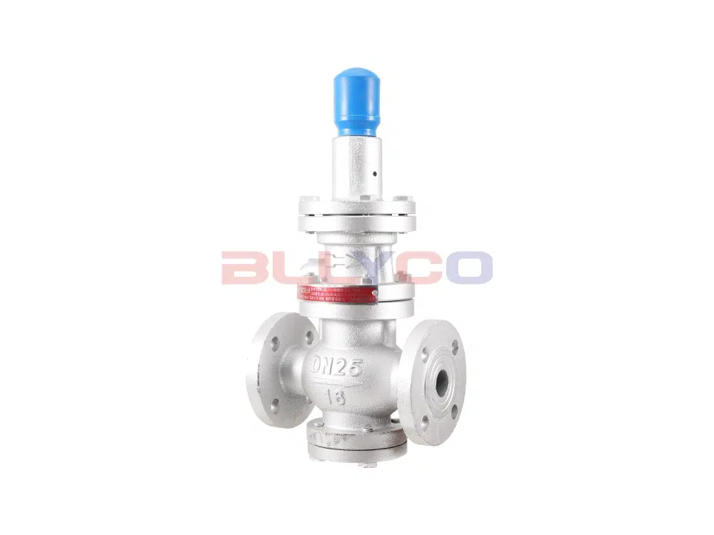
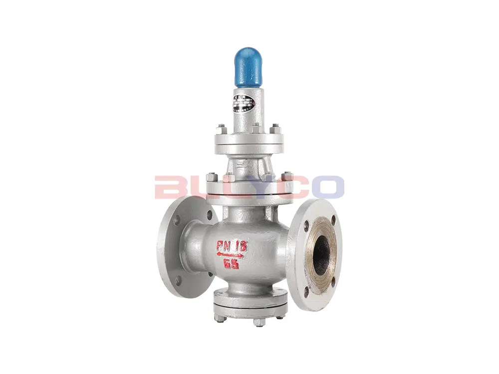
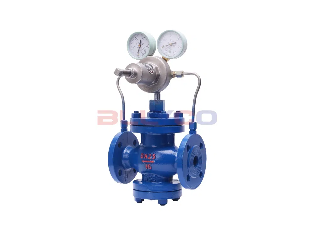
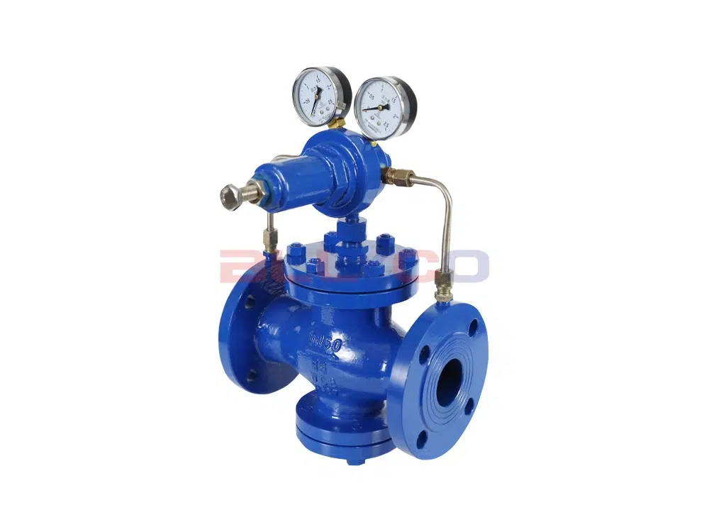
For pressure reducing valves, in addition to the 19 items specified for general valves, the markings on the valve body shall also include: date of manufacture, applicable medium, and outlet pressure.
For steam trap markings, in accordance with GB/T 12250-2005, the markings may be affixed to the valve body or displayed on a nameplate.
The marking of safety valves shall comply with the provisions of GB/T 12241-2005.
Ball valves, parallel gate valves, and plug valves shall be marked in accordance with API 6D-2014.
The sealing surface material code for surfaces machined directly from the valve body is denoted by “W”. Codes for other materials are listed in the table below.
Seat sealing surface or lining material code:
Seat sealing surface or lining material | nicknames | Seat sealing surface or lining material | nicknames |
Tin-based bearing alloys (pasteurized alloys) | B | Nylon Plastic | N |
enamels | C | Boron-infiltrated steel | P |
nitriding steel | D | lead lining | Q |
fluoroplastic | F | austenitic stainless steel | R |
ceramics | G | plastics | S |
Cr13 stainless steel | H | Copper Alloy | T |
rubber lining | J | caoutchouc | X |
Monel alloy | M | Cemented carbide | Y |
Note: When the sealing surfaces of a sealing pair are made of different materials, the designation code of the softer material shall be used.
For gate, globe, and check valves, as well as ball and butterfly valves, the sealing specific pressure qMF must be less than the sealing specific pressure q, and the sealing specific pressure is less than the sealing allowable specific pressure [q] (i.e., qMF < q < [q]).
The shell test pressure for general-purpose valves is 1.5 times the rated working pressure of the material at 38°C. The high-pressure seal test is 1.1 times the rated working pressure of the material at 38°C. Low-pressure seal test requirements vary by standard.
Among these:
GB/T 13927-1992, ISO 5208:2008, EN 12266.2-2012 is 0.6MPa±0.01MPa;
GB/T 26481-2011, API 598-2009 is 0.4MPa~0.7Mpa;
MSS SP61-2013 is 0.56 MPa;
API 6D-2014 for Type I: 0.034MPa~0.1MPa, Type II: 0.55MPa±0.69MPa;
ISO 14313:2007 for Type I: 0.05MPa~0.1MPa, Type II: 0.55MPa±0.07MPa;
API 6A (idt ISO 10423:2003) for PSL3G: first: rated pressure, second: 2.0MPa ± 0.2MPa; PSL4: first: rated pressure, second: 2.0MPa ± 0.2MPa.
sports event | Applicable temperature |
High temperature valve | Medium working temperature greater than 450 ℃ |
Heat-resistant valves | Medium working temperature above 600℃ |
Cryogenic valves | Medium working temperature in -29 ℃ ~ -100 ℃ |
Ultra-low temperature valve | Medium working temperature less than -100℃ |
sports event | Nominal size |
Extra large caliber valves | DN≥1400mm |
Large Caliber Valve | DN350mm~1200mm |
Medium caliber valves | DN50mm~300mm |
Small diameter valves | DN≤40mm |
sports event | Nominal pressure |
Ultra High Pressure Valves | PN≥100MPa |
High Pressure Valves | PN10.0MPa~80.0MPa |
Medium Pressure Valves | PN2.5MPa~6.4MPa |
Low Pressure Valves | PN≤1.6MPa |
Classification of valves based on their purpose or primary structural characteristics.
General classification categorizes valves by both operating principle and structure, representing the most widely used classification method domestically and internationally. Common types include: gate valves, globe valves, plug valves, ball valves, butterfly valves, diaphragm valves, check valves, throttle valves, safety valves, pressure reducing valves, steam traps, and control valves.
Valve model designations are composed of codes representing valve type, actuation method, connection type, structural configuration, sealing surface material or lining material type, pressure rating or working pressure at operating temperature, and valve body material.
The valve model consists of seven parts, with their meanings shown in the diagram.

NPS:
Combined alphanumeric size designation for piping system components consisting of the letters NPS followed by a dimensionless integer number. This number is directly related to a characteristic dimension such as the bore or outside diameter of the end connection. The dimensionless number may be used as a dimensional designation for valves without the prefix “NPS”. Dimensionless size numbers do not represent measured values and cannot be used for calculations.
Class:
A combination of letters and numbers used to identify the pressure/temperature capability of a valve in relation to the mechanical and dimensional properties of the valve material. It consists of the letter Class followed by a dimensionless integer. The number following the letter Class does not represent a measured value and should not be used in calculations. The permissible pressure of piping elements depends on the Class value, the material and the permissible working temperature, unless otherwise specified in the respective standard. The permissible pressures are given in the pressure-temperature rating tables of the respective standards.
DN:
A combination of letters and numbers used to identify the size of piping system components. It consists of the letter DN followed by an integer number without a factor. This number is directly related to the characteristic dimensions of the end connection, such as the bore diameter or the outside diameter (expressed in mm).
Note:
PN:
A combination of letters and numbers used for reference purposes in connection with the mechanical and dimensional properties of piping system components. It consists of the letter PN followed by a non-factorized number.
Note:
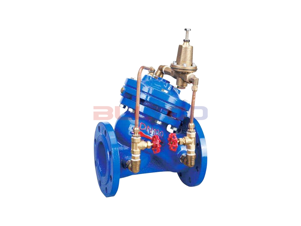
Valves commonly used in pipelines across various industrial enterprises.
A general term for mechanical products with movable mechanisms used to control the flow of media within pipelines.
![]()
Specialized in the development and production of fluid control valves
Our leading production:ball valves, butterfly valves, gate valves, globe valves, check valves, filters, water control valves, pressure reducing valves, balancing valves, regulating valves, pneumatic valves, electric valves, and other high, medium and low pressure valves.


Copyright © 2026, BolaiKong Technology (Wuxi) Co., Ltd. All rights reserved. 苏ICP备2024066753号-1 ![]() 苏公网安备32021402002554号
苏公网安备32021402002554号