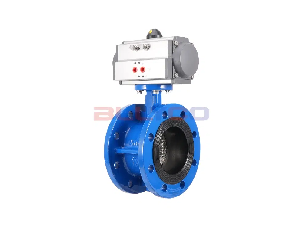
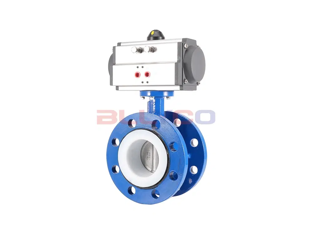
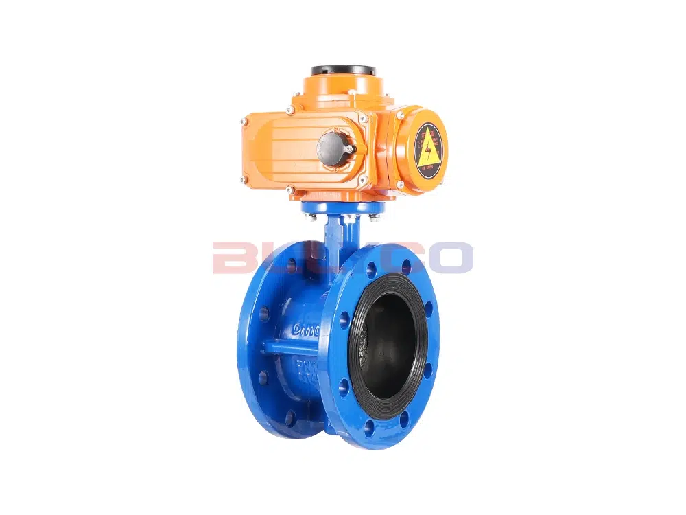
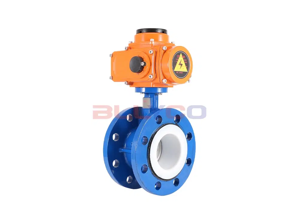
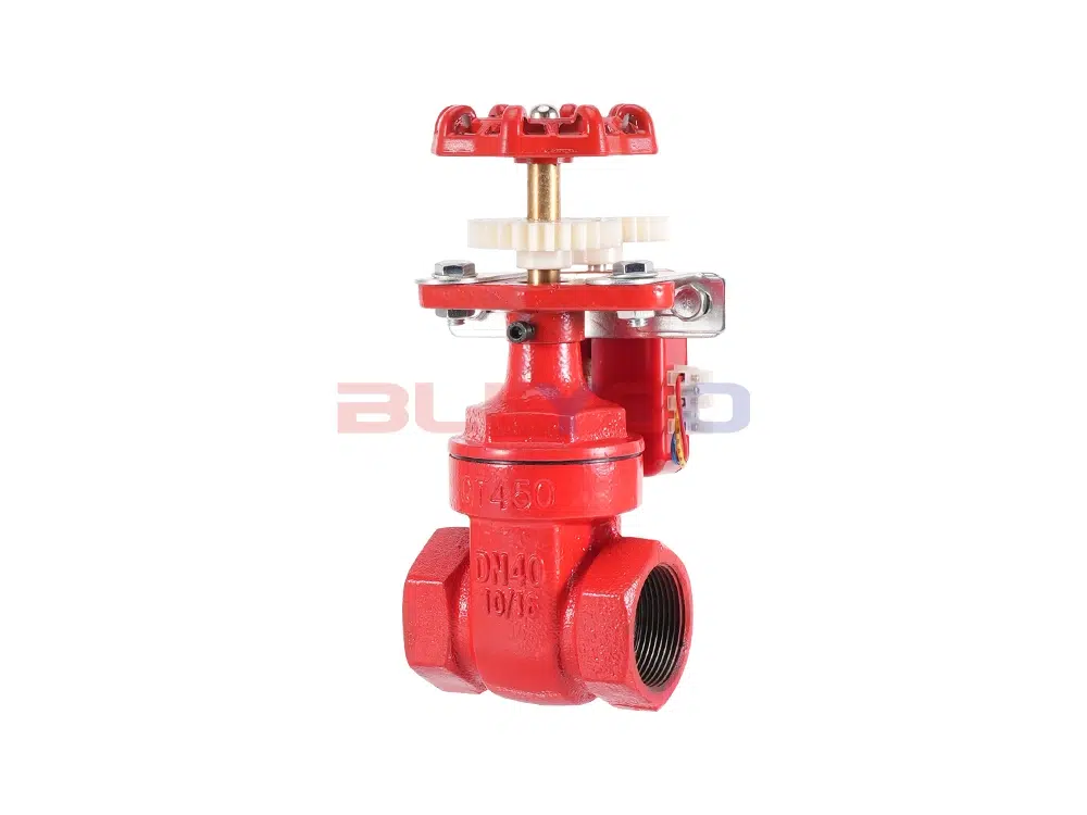
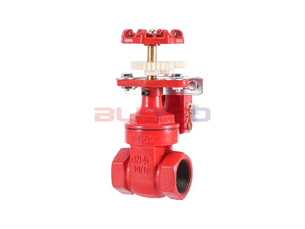
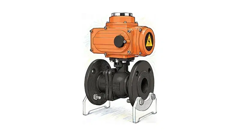
智能电动阀门
多种电压|精准控制|IP68防护等级
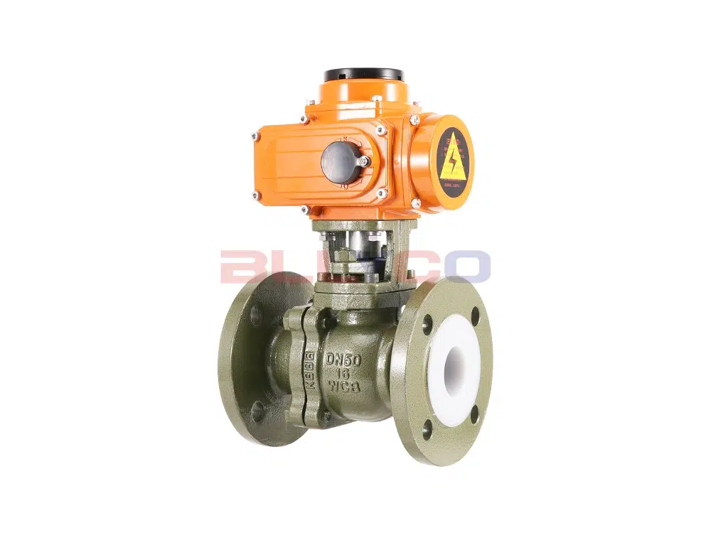
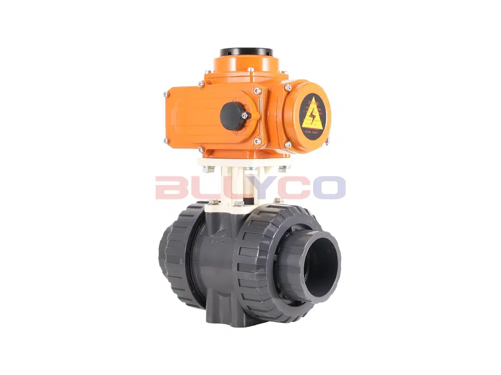
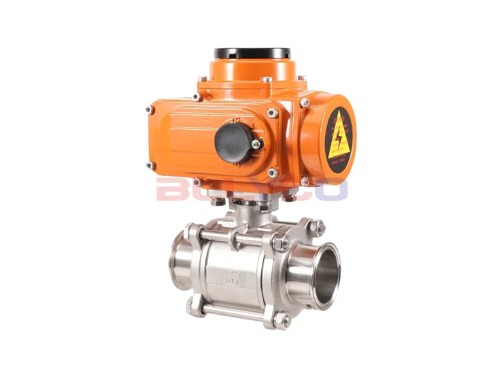
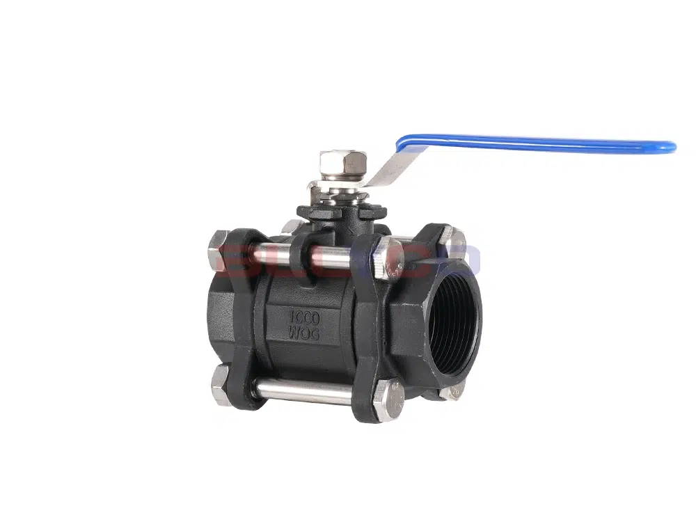
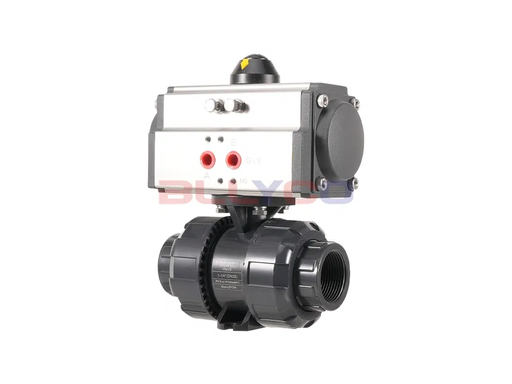
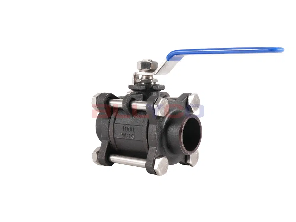
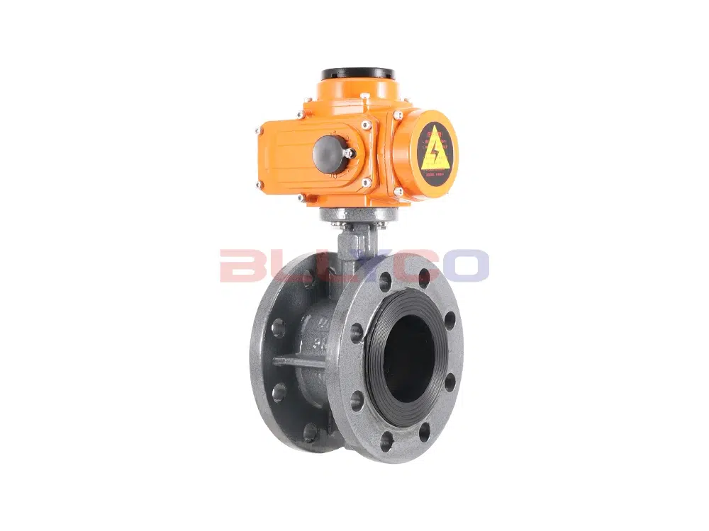
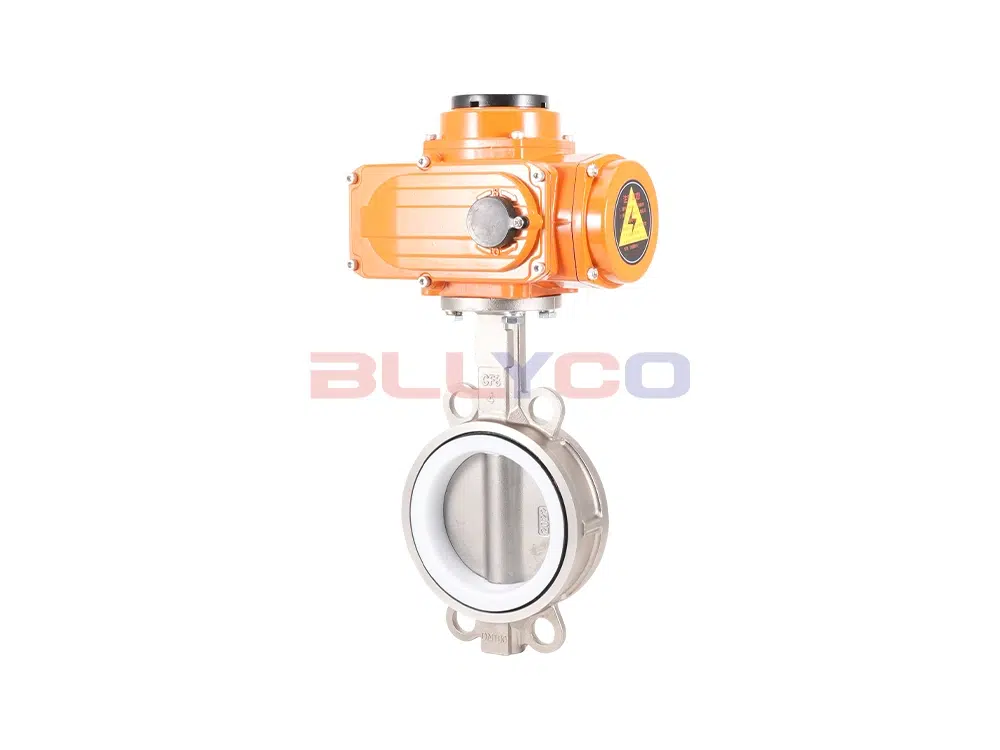
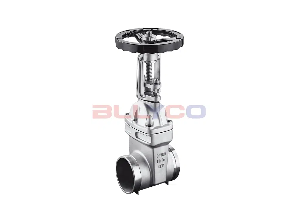
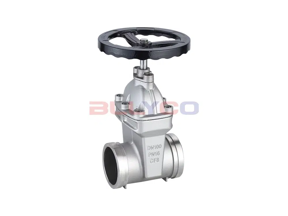
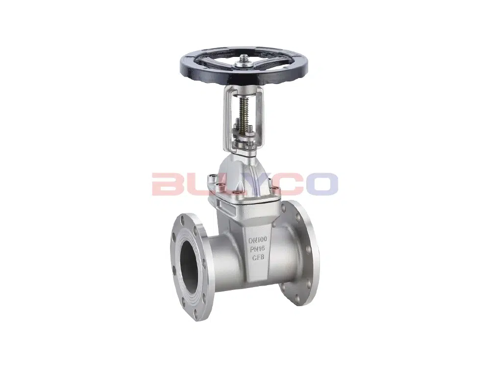
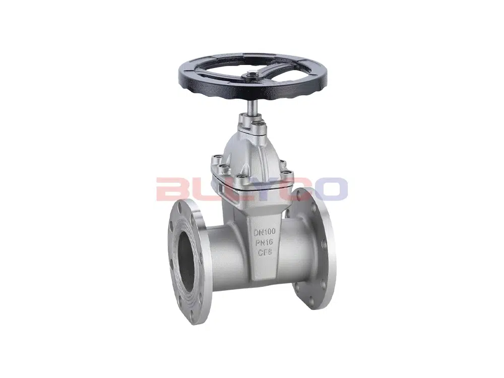
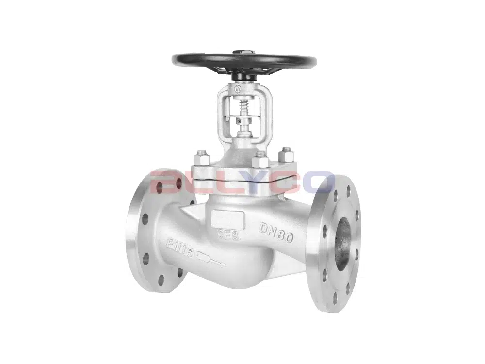
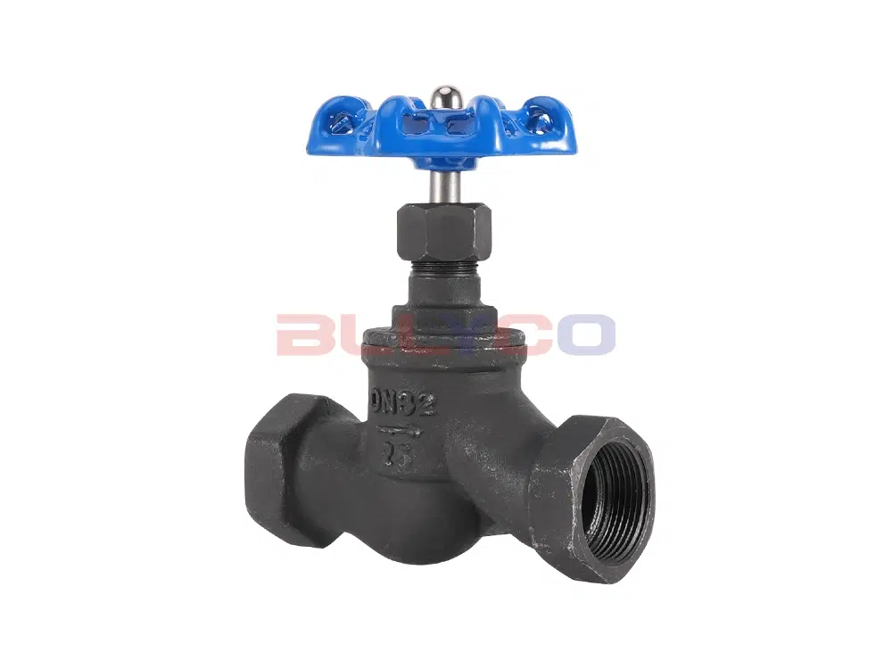
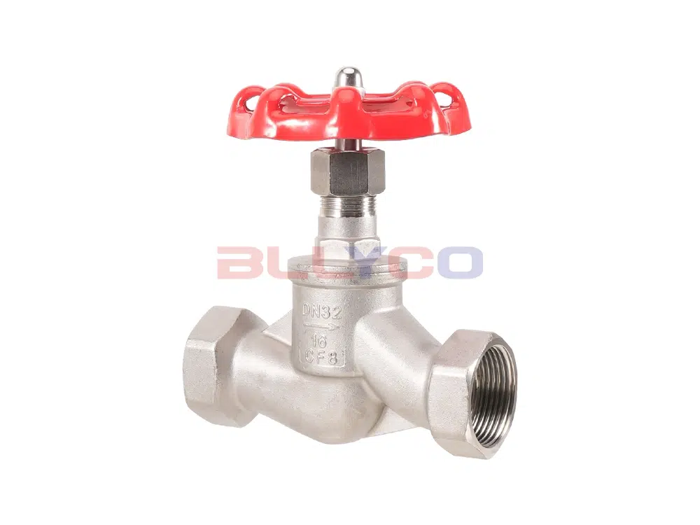
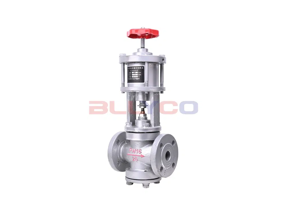
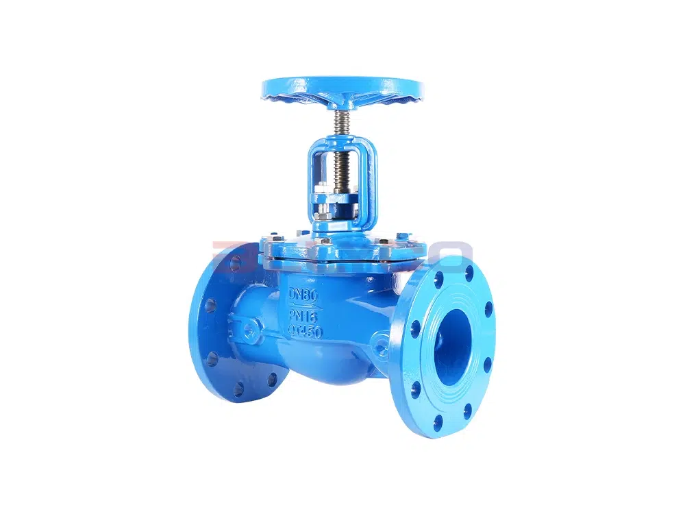
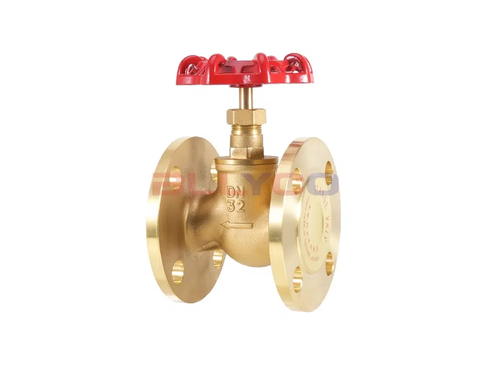
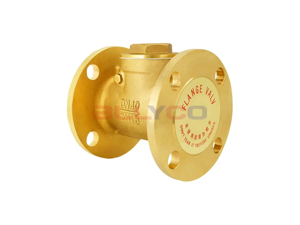
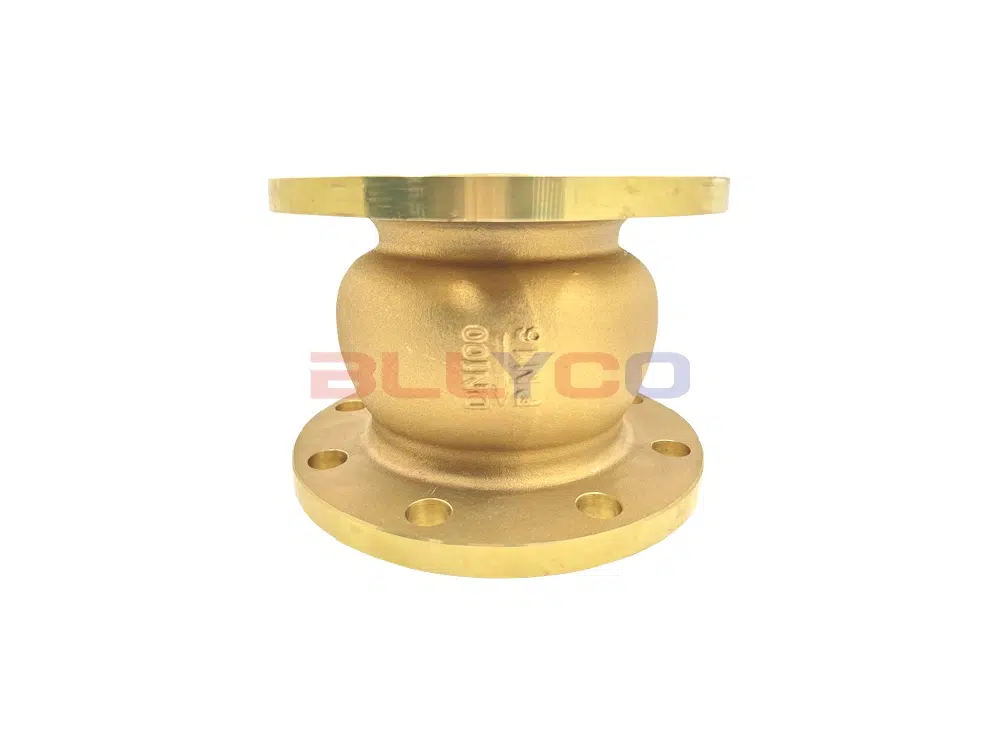
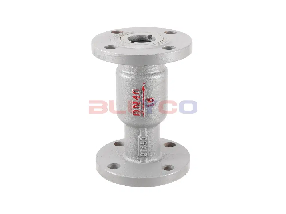
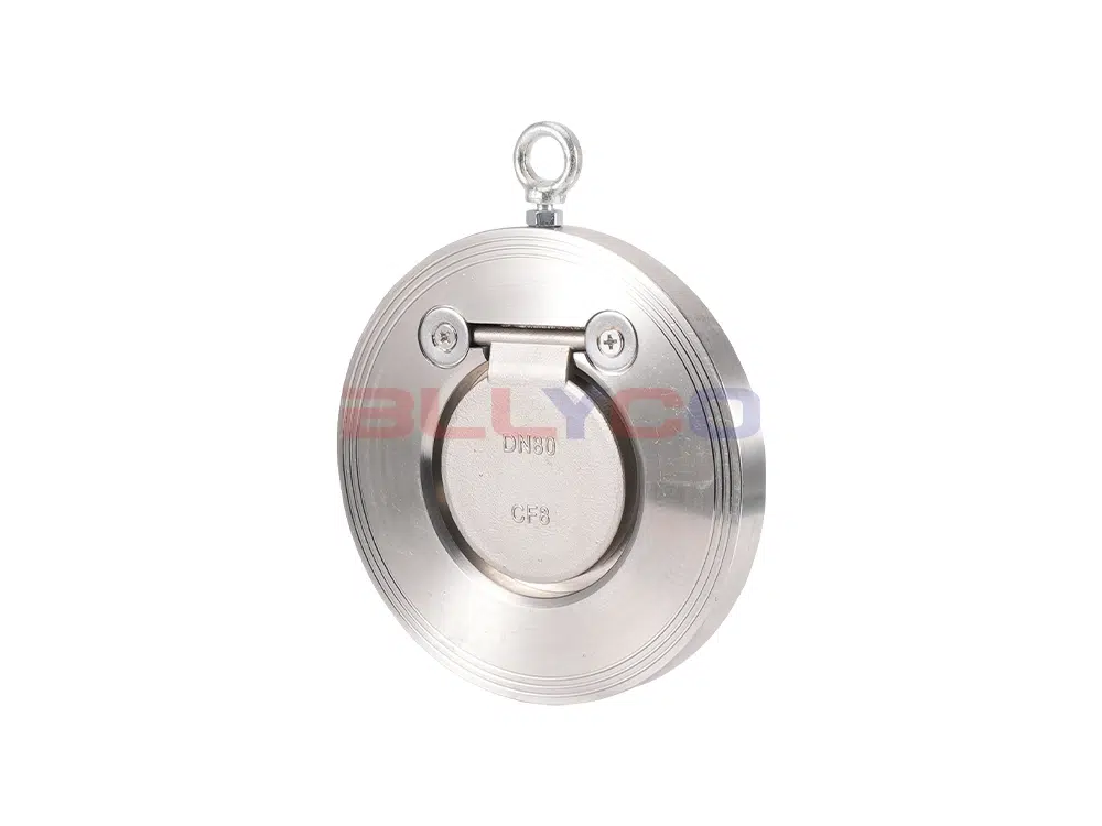
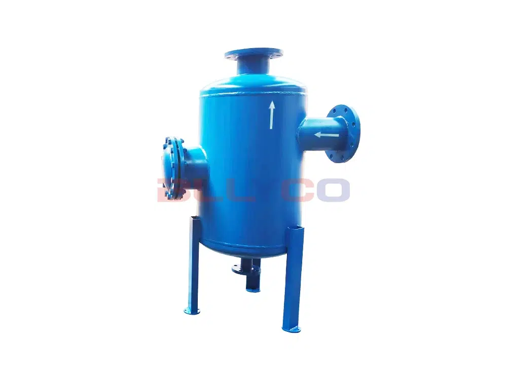
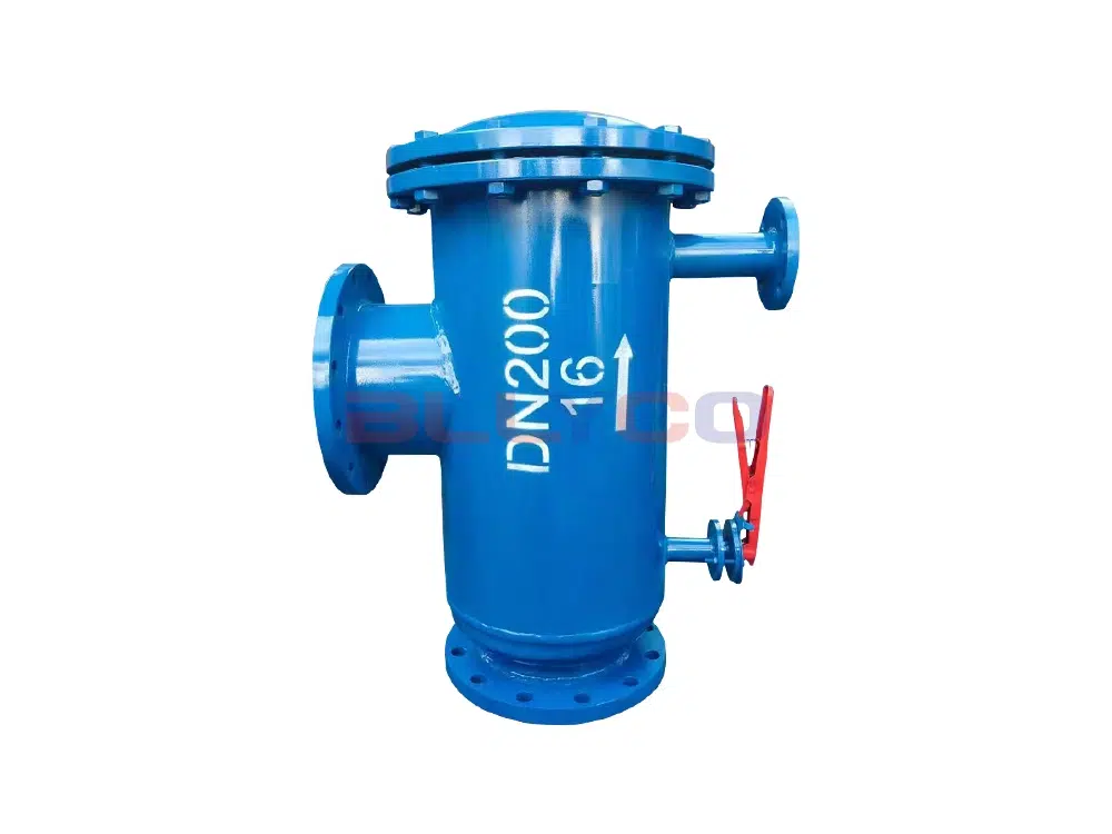
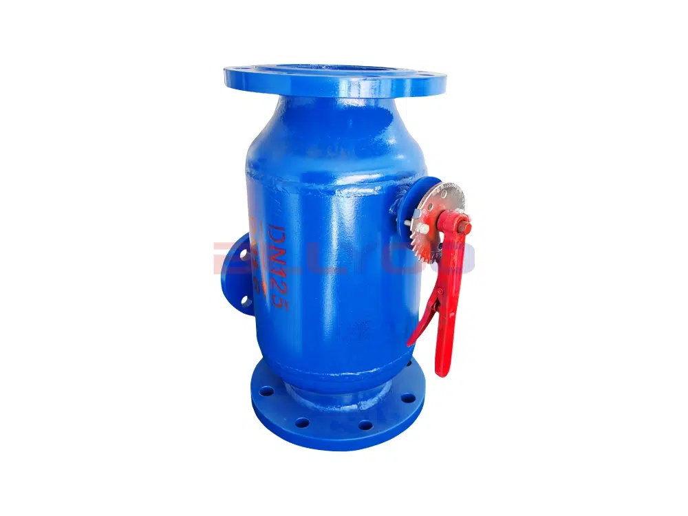
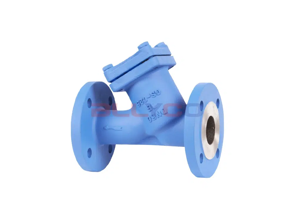
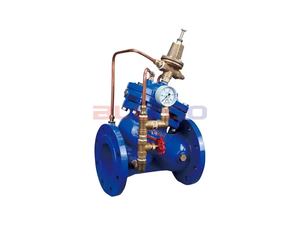
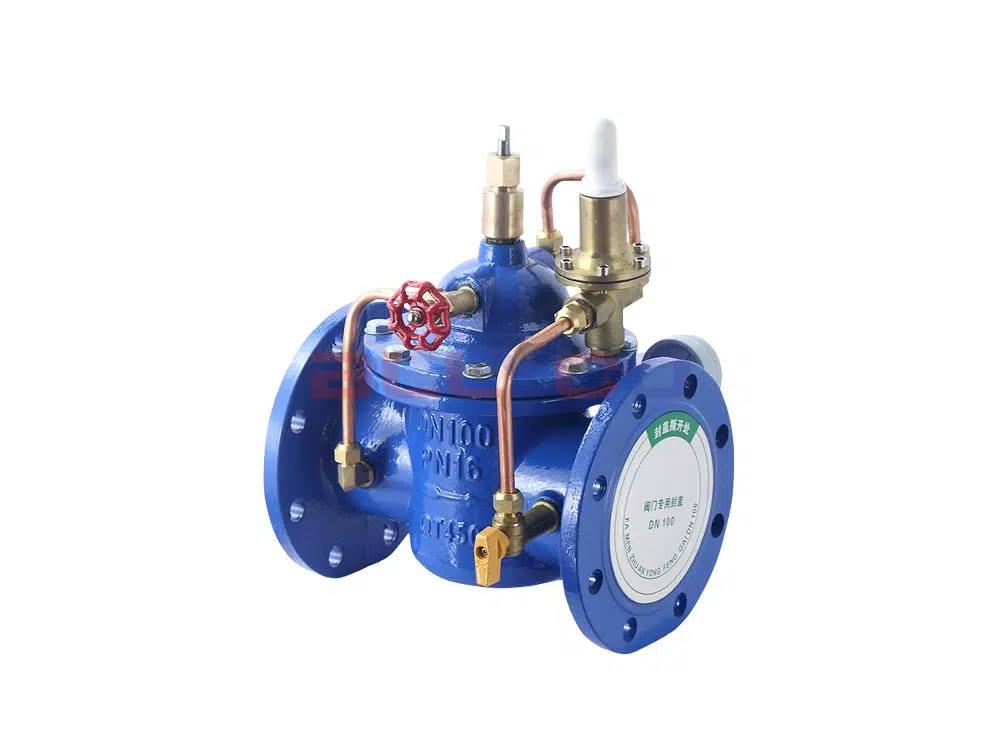
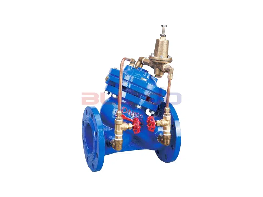
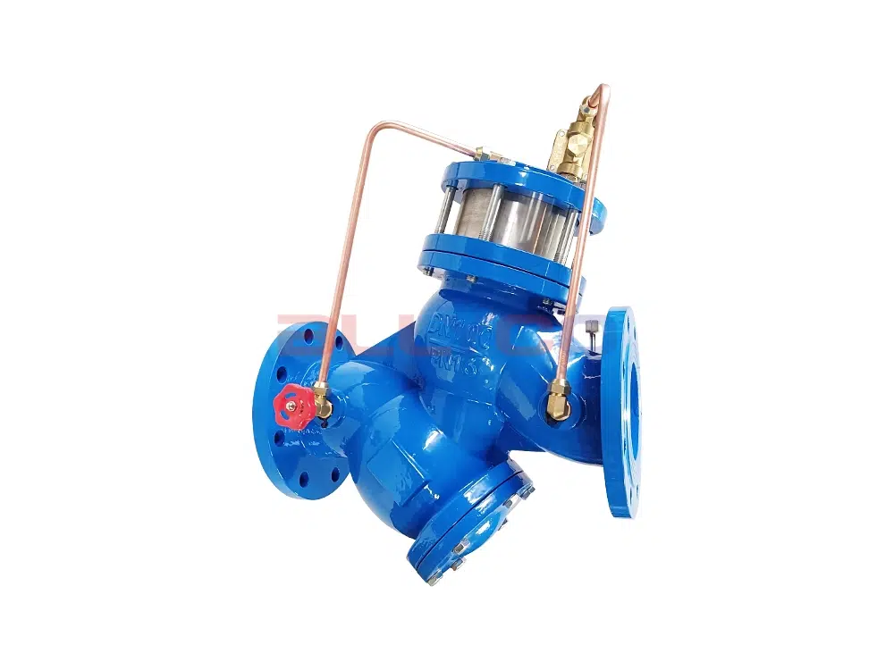
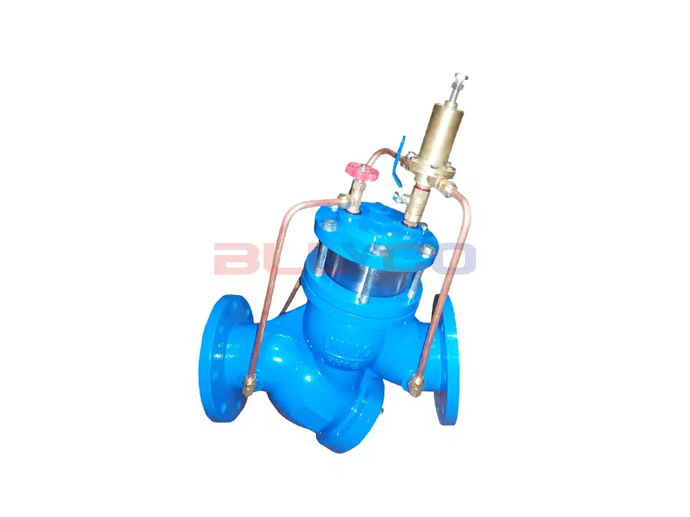
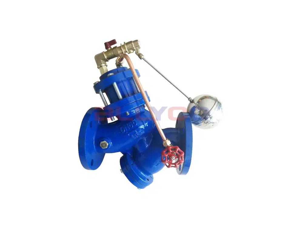
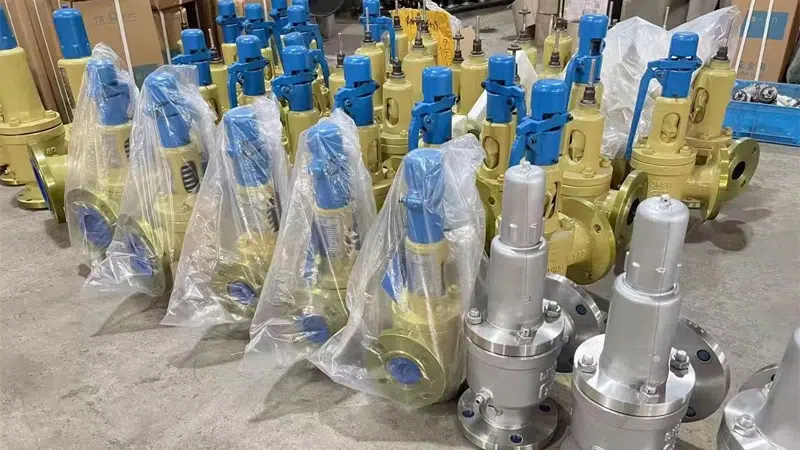
产品展示

服务保障
根据客户的实际需求确定阀门的型号及规格,也可以按照客户的特殊要求设计定制,并为客户提供阀门设计的流程,制造出符合客户要求的阀门。并可以为客户培训相关的技术人员,使其掌握一定的技术常识和阀门维护技巧。 提供新、特、难工程施工技术咨询或拟定合适的施工方案。


新闻中心
隔膜泵安全阀作用:守护系统稳定性
本文系统阐述了隔膜泵安全阀的核心功能、工作原理、选型要点及维护实践。安全阀作为关键的超压保护装置,通过自动开启释放多余压力,能有效防止隔膜破裂、管路爆裂等设备损伤,抑制水锤冲击,并保障工艺过程稳定与人员环境安全。文章分析了弹簧式、重锤式等主要阀型,并指出选型需综合考虑设定压力、流量能力、材料兼容性及介质特性。此外,通过介绍典型应用场景,并结合安装、维护要点与故障排查指南,辅以实际改造案例,论证了合理配置与维护安全阀对于提升系统可靠性、延长设备寿命及降低综合运维成本的重要价值。
电动球阀一直响怎么办?教你快速排查与长期解决之道
本文系统阐述了电动球阀异常噪音的诊断流程与长期管理策略。诊断方面,提出“听诊定位→断电检查→安装校正→润滑密封→电气排查”五步排查法,强调结合声音特征、手动测试与仪器检测进行精准判断。长期管理上,建议建立定期维护制度、优化备件管理、推动技术升级与加强人员培训,形成预防性维护体系。全文旨在帮助用户从被动维修转向主动管理,彻底解决电动球阀噪音问题。
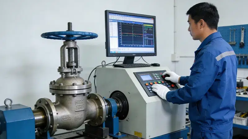
选择阀门第三方检测机构,保障安全与质量的最佳选择
阀门作为工业设备中的关键组成部分,在各类生产和运输过程中起到了至关重要的作用。选择专业的阀门第三方检测机构,是确保阀门产品质量、安全性和可靠性的有效途径。本文将深入探讨阀门第三方检测机构的重要性,以及如何选择合适的检测服务,帮助企业提升产品质量与竞争力。
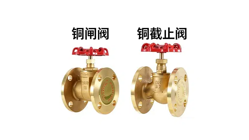
铜闸阀和铜截止阀的区别解析:选择适合你的阀门至关重要
铜闸阀和铜截止阀的选择在管道系统中尤为重要,它们各自有不同的特点与使用场景。了解这两者的区别,能帮助您在实际应用中做出更合理的决策,确保系统运行安全高效。
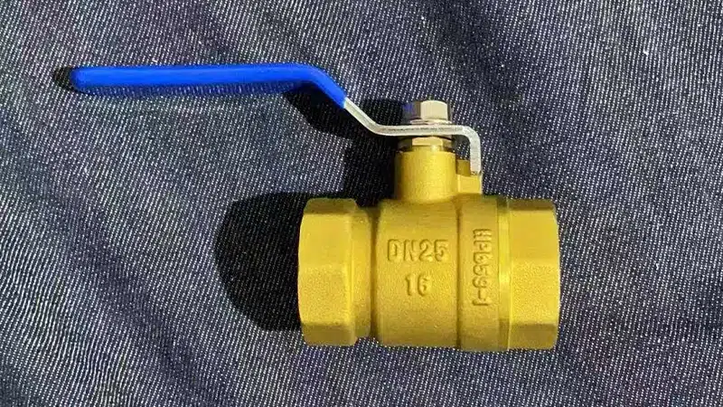
铜球阀尺寸对照表:选购与应用全攻略
了解铜球阀尺寸对照表,帮助您在选购铜球阀时轻松匹配正确规格,确保水管安装与系统运作的顺畅。掌握铜球阀的尺寸标准,优化管道配置与管理。
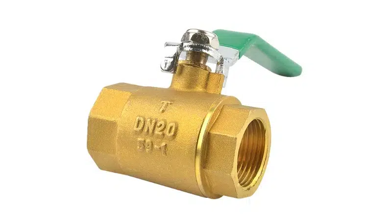
了解铜球阀型号规格尺寸:选择合适铜球阀,保障工程安全高效
铜球阀作为管道系统中常用的重要控制元件,广泛应用于自来水、暖气、燃气等领域。了解铜球阀的型号、规格、尺寸及其选择方法,能够帮助用户在众多选择中找到最适合的产品,提高工程的安全性和效率。
与我们取得联系
如果还有什么疑问可以在线给我们留言,我们会尽快给您回复,如果您想了解更详细的信息欢迎通过下面邮箱直接联系我们。
我们将提供:
- 30分钟快速响应,留言后24小时内回复
- 针对客户需求定制解决方案
- 时刻跟踪产品生产过程,尽量缩短生产周期
- 指导客户安装调试,售后快速响应
邮箱咨询:bolaikong@163.com